Cumulative Tolerance Build-Up Across Stacked Laminae
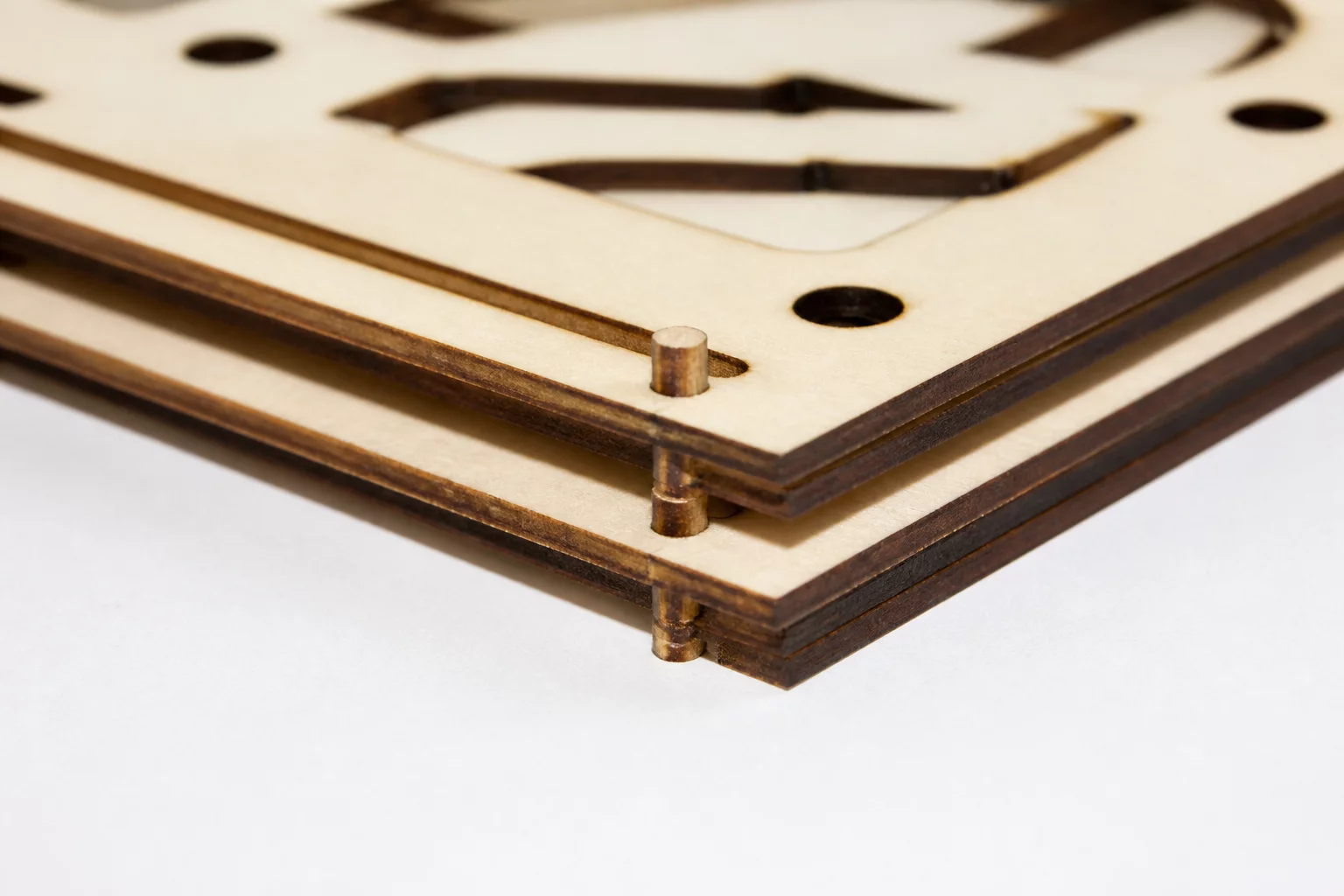
Stacking multiple laser-cut sheets exposes an engineering challenge distinct from single-joint fabrication: cumulative tolerance stack-up. In a single 3.0 mm plywood joint, a minor kerf variance of 0.04 mm rarely threatens mechanical utility. When stacking four or five identical plates registered with common dowels, however, minute directional variances accumulate across every successive layer. The resulting misalignment manifests as stepped perimeter edges, uneven face registration, and severe binding across vertical thru-pins.
During our laboratory trials with 5-tier birch plywood stacks, each individual cut profile exhibited an average conical kerf taper of 1.4 degrees from focal top to bottom exit. As successive sheets were positioned in identical cutting orientations, these taper vectors compounded sequentially. Plates stacked with identical top-face alignment retained an edge step of 0.18 mm across a 15 mm total stack thickness. Reversing every alternating plate face mitigated overall perimeter stepped drift to less than 0.05 mm, highlighting the critical role of material orientation in multi-ply fabrication.
Access our full laboratory protocol for calibrating beam spot size, focal height, and slot draft compensation across multi-ply sheets.
Registration Pin Sizing and Hole Clearance Dynamics
Precise registration demands intentional differentiation between locating holes and structural fastening apertures. Utilizing standard 4.0 mm wood dowels across five layers showed that a nominal 4.0 mm circular vector cut without inward kerf compensation yielded an oversized hole measuring 4.16 mm at the beam entry and 4.08 mm at the beam exit. This cumulative looseness allowed rotational play exceeding 1.2 degrees across opposite corners of a 120 mm square assembly.
Key Multi-Layer Calibration Insights
- Apply a dedicated inward kerf offset of 0.075 mm exclusively on registration dowel holes to maintain a press-locating interface.
- Design asymmetrical locator pin patterns (such as uneven 3-pin geometry) to mechanically prevent inverted assembly errors during glue-up.
- Cut nested alignment layers from adjacent sheet zones to maintain homogeneous core density and identical moisture levels across all tiers.
Mitigating Laser Draft and Adhesive Hydrodynamics
A secondary factor disrupting multi-tier alignment is adhesive squeeze-out under clamping pressure. Viscous PVA or aliphatic resins introduce hydraulic film thickness between layers, expanding total stack height by roughly 0.06 mm per joint interface. In a six-layer stack, this adds over 0.30 mm of vertical drift, which binds dowels that rely on tightly machined depth stops or shoulder tabs.
Our test coupons verified that cutting shallow interior adhesive relief reservoirs (etched pockets with 0.4 mm depth) adjacent to the perimeter slots provides an escape channel for excess glue. This technique eliminated vertical hydraulic lift and preserved true edge alignment without requiring excessive clamping force that could bow thin external laminae.
Multi-Layer Alignment FAQs
Pin binding occurs primarily due to the natural conical draft angle of the focused laser beam. Each layer possesses slightly different diameters at its top and bottom surfaces. When multiple tapered holes are stacked, the concentric centerlines drift slightly unless compensation offsets are tuned specifically for dowel clearance.
No. Internal holes and external perimeters experience differing heat concentrations and beam entry geometries. Internal locator holes require an inward offset approximately 0.02 mm looser than tight structural slots to facilitate smooth manual alignment pin insertion across multiple stacked plates.
Incorporate engraved relief gutters or shallow score lines near alignment pins and joint borders. These pathways capture surplus adhesive under clamp compression, preventing hydraulic hydroplaning between mating surfaces.

David Wright
Related Slot Tolerances
Technical Discussion
Peer Calibration NotesNo comments yet. Be the first to leave a technical observation.
Leave a Technical Observation