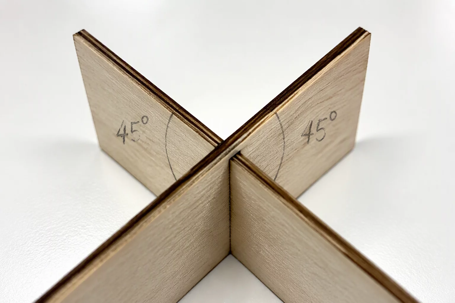
The Trigonometry Behind Non-90° Laser Slots
In standard orthogonal joints, cutting a slot equal to sheet thickness minus total beam kerf yields a dependable friction fit. The moment components interlock at an acute or obtuse angle, that basic formula fails completely. The effective path length through which the intersecting mating sheet must pass expands along the hypotenuse of the cut angle. As a direct result, a 3.00 mm sheet entering a slot tilted at 45° actually demands a slot opening of approximately 4.24 mm along the surface plane.
In our bench trials with 3.15 mm Baltic birch and 4.00 mm cast acrylic, ignoring this trigonometric expansion caused severe edge binding, cracked acrylic tabs, and delaminated veneer. Laser beams cut perpendicular to the flat sheet face, creating vertical straight edges rather than beveled wall surfaces. This vertical profile means the leading and trailing diagonal corners of the mating part strike the interior slot corners prematurely unless specific clearance adjustments are engineered into the CAD geometry before toolpath generation.
Learn how we quantify beam waist diameter, focal lens depth of focus, and directional axis variance across multi-batch substrates.
Empirical Fit Trials across 30°, 45°, and 60° Mating Angles
We prepared thirty calibration coupons across two material batches using a 60W CO2 laser with a calibrated beam kerf of 0.18 mm. By varying the CAD slot width using the formula W_slot = (T_material / sin(θ)) - KerfCompensation, we evaluated both ease of insertion and rotational rigidity under dry assembly conditions. The 45° coupon required an additional 0.08 mm dynamic relief radius at internal corners to clear the vertical edge artifact left by the cylindrical laser beam.
Core Laboratory Findings
- Nominal material thickness must be divided by the sine of the intersection angle prior to subtracting kerf width.
- Un-beveled 90° laser cut edges create contact points on opposite top and bottom corners, requiring corner dogbone reliefs for steep angles under 40°.
- Plywood displays minor core crushing that forgives up to 0.06 mm of error, whereas rigid cast acrylic shears if undersized by as little as 0.02 mm.
Beam Taper and Practical Joint Assembly
A standard 2.0-inch focal lens produces an hourglass beam profile with a slight conical taper along the cut thickness. When slots are cut at steep angles, this taper compounds the geometric mismatch. Setting the focal waist exactly at mid-thickness (50% depth into the substrate) balances the top and bottom edge widths, minimizing one-sided binding during assembly.
For production assemblies intended for glue-less friction locks, we recommend adding micro-ribs or 0.05 mm lead-in chamfers to the slot mouth. This geometry guides the angled tab smoothly into the joint pocket without chipping outer veneers or scuffing acrylic surfaces.
Frequently Asked Questions on Angled Joint Fits
Because laser cutters cut perpendicular to the sheet plane, creating straight vertical edges. When a sheet slides in at 45°, its top-front edge and bottom-back edge create an effective thickness equal to material thickness multiplied by 1.414. Without CAD width expansion, the opposing corner points collide instantly.
Design your slot rectangles in CAD using the trigonometric formula (Thickness / sin(Angle)). In LightBurn, apply the global Kerf Offset tool on the cut layer to compensate for the beam diameter without having to redraw complex polygon vertices manually.
For angles between 60° and 90°, standard corner clearance is usually sufficient. For acute angles below 45°, adding small circular dogbone reliefs (0.5 mm to 1.0 mm radius) at internal acute vertices prevents the beam radius from blocking full tab seating.

James Miller
Related Slot Tolerances
Technical Discussion
Peer Calibration NotesNo observations recorded yet. Be the first to submit a calibration report for this case.
Leave a Technical Observation