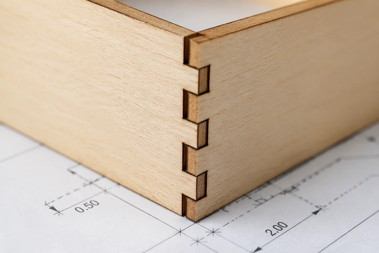
The Geometry Challenge of 90-Degree Laser Joints
When assembling laser-cut components at right angles, standard nominal dimensions often lead to binding, bulging corners, or loose seams. The laser beam cut is inherently cylindrical with a focal waist, meaning inside corners always retain a microscopic radius rather than a sharp zero-radius angle. If a square male tab attempts to seat inside an uncompensated square slot, this residual corner radius prevents the tab from bottoming out completely.
Through systematic coupon tests on 3.0 mm birch plywood and 3.0 mm cast acrylic, we recorded how varying kerf offset values and adding minor corner relief features (dog-bone or T-bone fillets) eliminates assembly resistance without sacrificing friction stability.
Learn how beam focal depth and laser speed variations influence actual kerf width before setting joint tolerances.
Empirical Clearance Values and Corner Reliefs
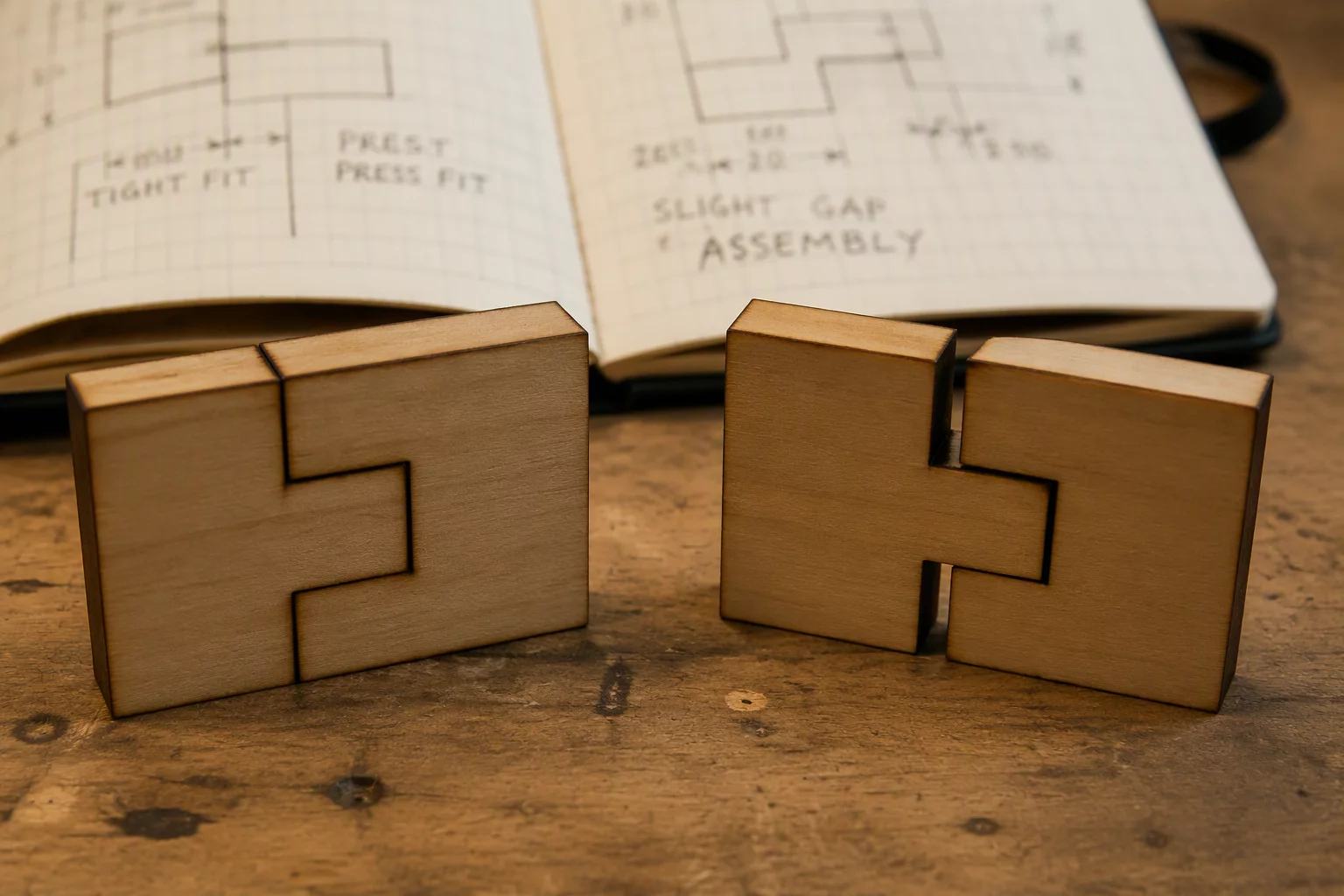
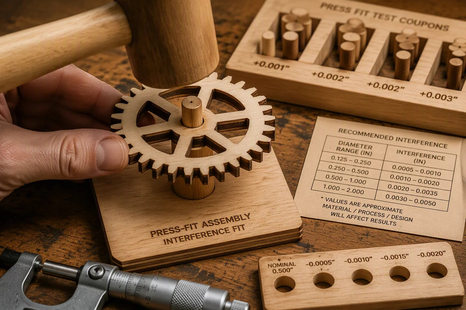
In our test series across ten consecutive test coupons, a bilateral kerf compensation of +0.08 mm produced an interference press fit in Baltic birch, whereas a +0.05 mm offset provided a clean slide-fit requiring zero sanding. When cutting sharp interior corners without fillets, the laser beam spot (typically 0.12 mm to 0.18 mm diameter depending on lens focal length) left an inside corner radius of roughly 0.07 mm, which created noticeable standoff on mating parts.
Key Clearance Findings
- Standard 90-degree internal corners require an additional 0.04 mm to 0.06 mm clearance to clear the laser beam turnaround radius.
- Dog-bone relief notches with a diameter matching the beam kerf allow sharp rectangular tabs to seat flush against interior faces.
- Cast acrylic requires 0.03 mm wider clearance than plywood to prevent stress fractures during snap assembly.
Recommended Joint Layouts and Practical Notes
To achieve reliable perpendicular assemblies in production runs, design male tabs with a slight chamfer or lead-in radius (0.2 mm) on the leading edges. This facilitates initial insertion while allowing the main friction faces to engage smoothly. When using LightBurn, applying precise inward or outward kerf offsets at the layer level ensures that slot widths match the actual measured thickness of each material batch.
Repeated assembly tests also demonstrated that friction joints in plywood loosen slightly after 3–4 assembly cycles due to fiber compression, whereas acrylic maintains consistent friction resistance throughout repeated cycles provided no micro-cracking occurs at internal sharp corners.
Frequently Asked Questions on Corner Clearances
The round profile of the focused laser beam prevents inside corners from being perfectly sharp 90-degree angles. This microscopic inside radius stops the square corners of mating tabs from fully seating. Adding a tiny corner overcut (dog-bone relief) or applying a 0.05 mm slot clearance solves this issue.
For 3.0 mm Baltic birch cut with a standard 2.0-inch focal lens, a one-sided kerf offset of 0.06 mm to 0.08 mm typically provides a snug, glue-free friction fit without inducing excessive splitting stress along the grain.
Yes. Acrylic is brittle and highly susceptible to notch sensitivity. Internal sharp corners concentrate mechanical stress, leading to hairline fractures during assembly. Small circular reliefs distribute the stress evenly across the joint.

James Miller
Related Slot Tolerances
Technical Discussion
Peer Calibration NotesTaylor
Verified MakerCorner joints finally make sense now.
Leave a Technical Observation