Diagnosing the Causes of Joint Play and Excessive Kerf Loss
A loose fit in laser fabrication occurs when the cut slot exceeds the physical thickness of the mating tab by more than 0.12 mm. This gap strips the assembly of friction, causing panels to wobble or disconnect under minimal structural load. Beam vaporization creates natural material loss along both cutting contours, compounding nominal gauge variations found in sheet stock.
In standard 3.0 mm birch plywood, laser beam kerf removes approximately 0.15 mm to 0.22 mm of total width depending on focal depth and assist pressure. If the vector file allocates a theoretical slot of 3.00 mm without inward compensation, the actual physical opening expands to 3.20 mm while the mating tab contracts to 2.80 mm. The resulting 0.40 mm total clearance produces structural collapse unless corrected.
Access our full testing methodology to determine step-by-step beam metrics before cutting entire sheets.
Software Adjustments and Mechanical Intervention Techniques
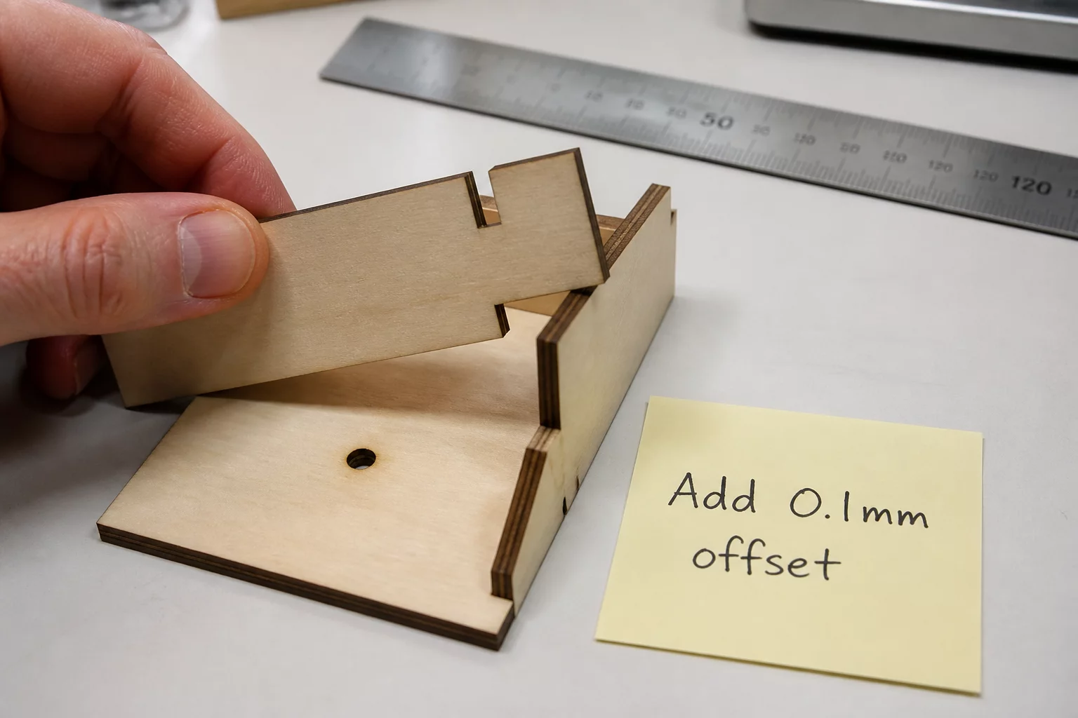
Solving loose fit scenarios requires differentiating between pre-cut digital adjustments and post-cut physical salvage. Within cutting software such as LightBurn, applying an outward kerf offset of 0.08 mm to 0.11 mm on inner contours reduces the finished aperture back to true gauge dimensions. When whole components are already cut and unusable as-is, physical intervention prevents substantial raw material waste.
Key Recovery Strategies
- Apply a +0.09 mm kerf offset to closed slot perimeters in your CAM layout to tighten subsequent runs.
- Integrate micro-crush ribs (0.15 mm semi-circular bumps) along slot walls to bridge batch variance.
- Employ laser-cut wooden shim wedges or high-viscosity PVA gap-fillers to stabilize already fabricated panels.
Long-term Prevention with Elastic Interference Geometry
Modern tab-and-slot design increasingly avoids flat, straight-edge mating walls because natural material tolerances fluctuate up to 10% across a single plywood sheet. Designing flexible snap tabs or spring ribs into the digital geometry accommodates loose zones without requiring custom toolpaths for individual board batches.
Testing coupons with graded micro-offsets before launching nested production runs guarantees repeatable friction fits. Documenting these calibrated offsets creates a reliable workshop baseline across moisture levels and varying laser tube ages.
Frequently Asked Questions on Loose Fits
Most standard CO2 laser setups with a 2.0-inch focal lens require between 0.07 mm and 0.12 mm of inward kerf offset on inner slot geometries to achieve a firm friction lock.
Yes. Physical parts can be reinforced by inserting thin veneer shims, applying cyanoacrylate or PVA bead swelling along the tab edges, or utilizing mechanical wooden cross-pins.
Bed level discrepancies, optical mirror misalignment, and material warping shift the focal point across large work surfaces, causing local variations in laser beam width.

David Wright
Related Slot Tolerances
Technical Discussion
Peer Calibration NotesJordan
Fabrication TechLoose fit solutions saved my latest project.
Leave a Technical Observation