Physical Material Variance and Optical Kerf Dynamics
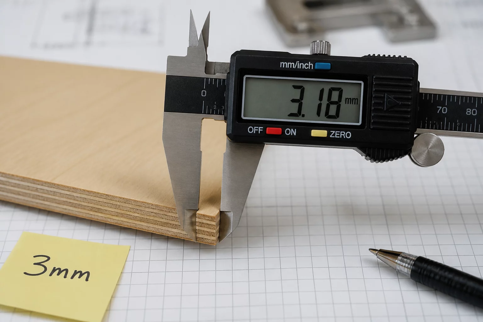
Commercial sheet stock manufactured for laser processing undergoes production tolerances that mills rarely control down to the tenth of a millimeter. In multi-ply hardwoods, variations in adhesive layer thickness, internal core voids, and localized hydraulic press pressures produce fluctuating cross-sections across a single 600x400 mm panel. When a designer provisions a 3.00 mm slot expecting a snug press fit, an actual sheet thickness of 3.28 mm turns a planned slide joint into mechanical binding, leading to fractured acrylic or splintered veneers.
Moreover, optical kerf alters dynamically across the focal waist as the beam penetrates inhomogeneous substrates. High-density core glues increase thermal dwell time, subtly expanding the kerf along the exit plane relative to the entry surface. Applying rigid kerf offsets in LightBurn without first measuring the physical stock at multiple points ensures assembly failures when scaling from single test coupons to nested production sheets.
Critical Metrology Rules for Precision Fitting
- 01
Mill Gauging Deviations Span the Entire Sheet
Digital micrometer sweeps show that nominal 3.0 mm Baltic birch sheets can range from 2.92 mm to 3.31 mm between different sectors of a single factory batch.
- 02
Manufacturing Process Governs Thickness Uniformity
Cell-cast acrylic exhibits pronounced surface gauge undulations across large sheets, whereas extruded acrylic provides tighter tolerance bands but melts with different kerf profiles.
- 03
Entry and Exit Planes Exhibit Hourglass Taper
Focused laser optics naturally form a converging and diverging beam waist, creating a microscopic V-taper along the cut edge that affects the true mechanical contact area of interlocking tabs.
- 04
Ambient Moisture Shifts Organic Material Thickness
Unsealed organic veneers absorb atmospheric moisture inside workshop environments, expanding physical cross-sections by up to 0.12 mm between initial morning cuts and final evening assembly.
Core Takeaways for Repeatable Joint Assemblies
Eliminate loose joints and broken parts by replacing nominal assumptions with systematic physical measurements before updating production files.
- Measure all four sheet edges and the center coupon with digital calipers before setting CAD slot widths.
- Cut stepped slot gauge coupons in 0.05 mm increments directly from the active sheet offcut.
- Apply empirical kerf offset values inside LightBurn cut layer settings rather than modifying vector geometries manually.
Standardized Pre-Cut Coupon Testing Protocol
Begin each fabrication run by trimming a 50x30 mm test coupon from the edge of the sheet intended for final production. Measure three distinct points along the coupon body using clean caliper jaws held perpendicular to the surface. Average these numbers to establish your true working stock thickness.
Run a five-slot test comb spanning -0.10 mm to +0.10 mm around your target interference fit using production speed, power, and air assist settings. Test friction engagement with an identical mating tab. The ideal connection should engage under smooth finger pressure without play or splitting, confirming your optimal LightBurn kerf compensation value.


Laboratory Comments
Sam
Fabrication SpecialistNominal thickness is a trap. Always measure with calipers!
Leave a Laboratory Note
Share technical feedback or empirical observations regarding laser kerf compensation.