
Deconstructing Kerf Variables in Laser Fabrication
When a focused laser beam vaporizes material along a vector path, it leaves a channel known as the kerf. The fundamental error encountered in LightBurn workflows is setting offset adjustments before testing the physical sheet batch. Variations in assist gas velocity, focal lens cleanliness, and directional optic beam polarization cause kerf widths to drift by more than 0.05 mm across identical machine profiles.
Treating kerf compensation as an experimental procedure requires running dedicated stepped test coupons before sending large files to cut. Cutting five graduated tenons in 0.02 mm increments alongside matching mortises enables operators to evaluate friction, snap-fit, and glue clearances under true operating feed rates.
Essential Principles of Empirical Fit Determination
- 01
Kerf Changes With Focal Distance
A minor 0.5 mm variance in bed level or nozzle standoff alters the beam spot diameter at the material surface, expanding or contracting the kerf channel.
- 02
Feed Rate and Thermal Blooming
Slower cutting speeds deposit excess thermal energy into organic substrates like plywood or MDF, creating a wider burn path compared to fast cutting passes.
- 03
Material Density and Moisture Drift
Internal voids and varying core moisture content alter laser absorption rates, making empirical coupon validation on the project sheet essential.
- 04
Inside vs Outside Vector Offset Logic
LightBurn applies kerf offsets outward on external contours and inward on interior cutouts. Selecting the wrong contour direction doubles geometric error.
Key Metrology Protocol Summary
A standardized coupon routine eliminates guessing, prevents wasted full-sheet stock, and delivers predictable interlocking assemblies.
- Always test kerf on an offcut from the identical production board under matching air assist pressure.
- Apply offset values in LightBurn layer settings only after physical caliper verification of gauge coupons.
- Document batch-specific kerf values in a laboratory journal to build reliable baseline profiles.
Step-by-Step Coupon Testing Workflow
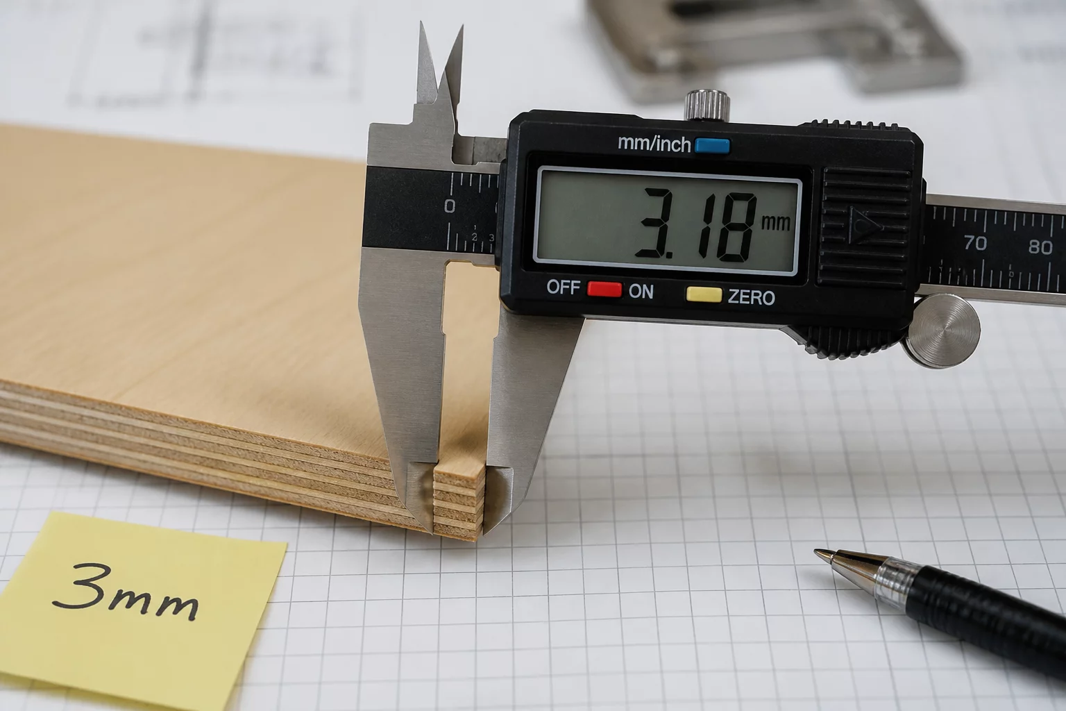
Start by cutting an array of 10 adjacent vertical strips measuring 10.00 mm wide each. Push the cut strips together inside a light clamp and measure the combined total length with digital vernier calipers. Subtracting this total from 100.00 mm and dividing the remaining gap by 10 cut lines provides the average beam kerf width for that laser power profile.
Once the baseline beam width is identified, cut a dual-sided interlocking gauge featuring stepped male tabs from -0.10 mm to +0.10 mm offset. Test the mechanical feel against mating slots to select the ideal interference fit for glue joints or toolless knock-down assemblies.

Laboratory Comments
No technical notes recorded yet for this protocol. Be the first to post a laboratory observation below.
Leave a Laboratory Note
Share technical feedback or empirical observations regarding laser kerf compensation.