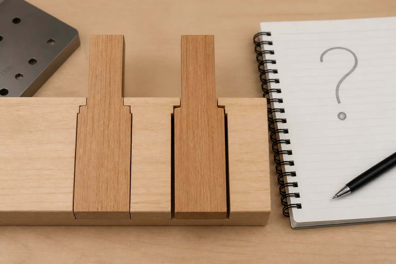
Root Causes of Conflicting Coupon Tolerance Results
Laser cutting creates an illusion of absolute geometric repeatability. Digital vector lines in software remain mathematically fixed down to the nanometer, yet the physical interaction between a focused photon beam and an organic substrate is governed by thermodynamics and fluid mechanics. When a secondary coupon diverges by even forty microns from the initial test, looking strictly at vector kerf offsets in LightBurn will not resolve the discrepancy.
The primary physical culprit in standard CO2 and diode machines is bed plane runout coupled with focal depth sensitivity. A short focal length lens with a 1.5-inch or 2.0-inch rating exhibits a tight depth of focus. A height deviation of merely one millimeter between bed quadrants expands the waist diameter of the spot. That focal expansion alters the kerf width and simultaneously introduces an angled taper to the cut walls.
Four Diagnostic Rules for Conflicting Fit Tests
- 01
Thermal Lens Warming & Shift
Optics absorb fractionally higher thermal energy over extended cut files. As the ZnSe focal lens warms, slight thermal expansion shifts the focal waist downward, widening kerf width in later cuts compared to cold-start coupons.
- 02
Bed Leveling and Honeycomb Bow
A sheet placed across an uneven honeycomb bed alters the focal distance as the laser head traverses from top-left to bottom-right. Always run confirmation coupons in the exact quadrant of your planned assembly.
- 03
Core Void and Internal Plywood Density
Natural variations in internal veneer plies, resin glue pockets, and moisture gradient alter laser burn rates. Two slots spaced four inches apart may exhibit measurable kerf differences inside identical sheets.
- 04
Air Assist Line Pressure Stability
Intermittent compressor cycles create variable nozzle pressure. Lower airflow fails to eject molten debris rapidly, resulting in localized over-burning and an expanded kerf gap on secondary cuts.
Verification Checklist Before Adjusting Software Offsets
Never change your software kerf offset settings after a single contradictory coupon. Execute this three-step isolation routine first:
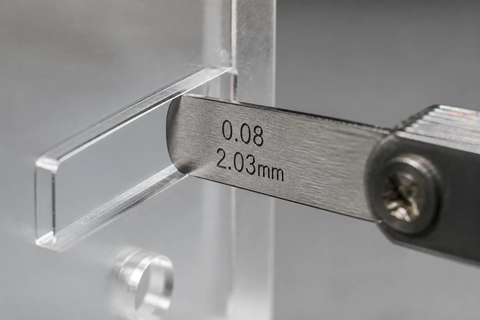
- Check physical focal height at both test locations using a stepped feeler gauge or manual focus block.
- Inspect lens cleanliness for soot condensation or scorching that causes beam scatter during continuous firing.
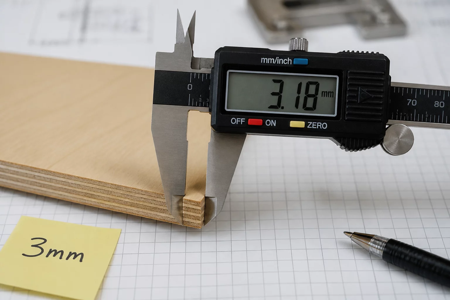
- Cut a dual-axis step coupon in the center and corner of the sheet to map localized variance before committing to production.
Protocol for Establishing a Production Compromise
When test results across a single material sheet show a repeatable spread of ±0.03 mm, aiming for an ultra-tight press fit across all joint locations is mechanically unrealistic. Fabricators should design tab and slot geometry with compliant features, such as slight lead-in chamfers or micro-crush ribs, that tolerate minor kerf fluctuations without splitting delicate veneers.
Document your findings with dated coupon archives. Record the ambient workshop humidity, compressor tank pressure, cutting sequence order, and lens focal length alongside the measured caliper dimensions. Over time, these empirical notes transform unexpected contradictions into predictable engineering parameters.

Laboratory Comments
No laboratory comments recorded yet. Be the first to submit your empirical test observations below.
Leave a Laboratory Note
Share technical feedback or empirical observations regarding laser kerf compensation.