Multi-Cut Stacking vs. Single Gauge Probing
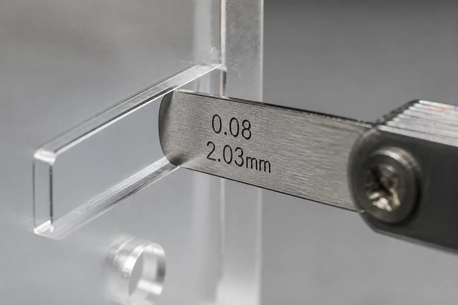
Measuring a single kerf line with conventional calipers introduces unavoidable edge deformation errors due to jaws pressing into charred kerf edges. The ten-cut block test isolates this variable by accumulating total material loss over ten adjacent rectangular coupons, dividing the composite gap across eleven distinct cut lines to yield sub-hundredth millimeter accuracy.
Laser beam profiles conform to a Gaussian intensity distribution where core photons deliver rapid vaporization while perimeter energy creates softened char margins. Evaluating beam width requires distinguishing between full material evacuation and the non-structural soot layer that collapses under joint assembly force.
Four Core Principles of Beam Kerf Metrology
- 01
Cumulative Ten-Cut Array Method
Cut a 100mm square divided into ten identical 10mm wide strips. Push the assembled strips tight against one edge and measure the remaining overall width. The difference divided by ten provides true empirical kerf per cut line.
- 02
Focal Plane Waist Alignment
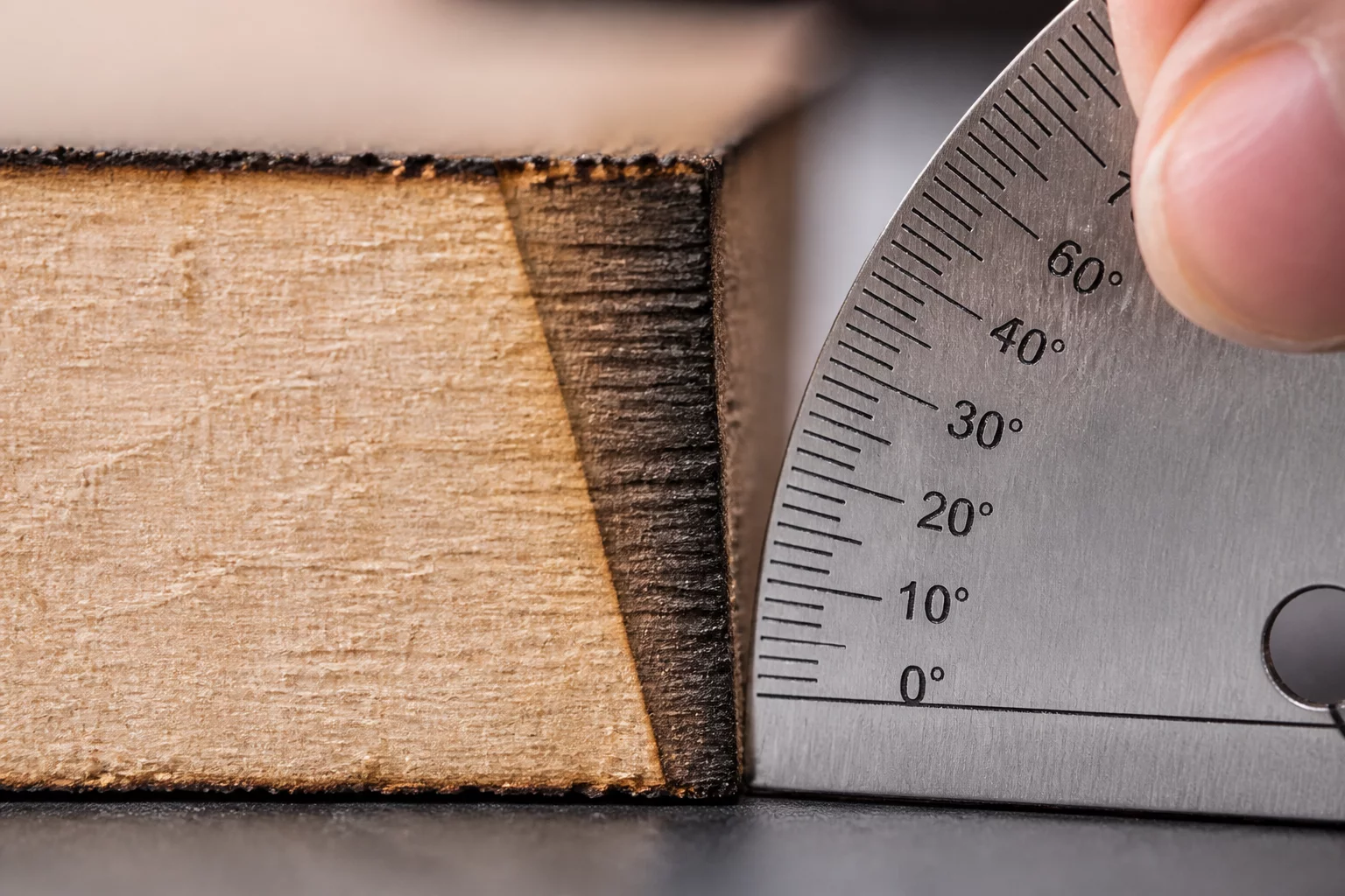
Ensure the focal beam waist sits precisely at the mid-depth of the stock gauge. When the waist drifts to the top or bottom surface, kerf taper widens the average measured channel.
- 03
Consistent Feed Velocity & Air Pressure
Accelerations and deceleration near corners alter local dwell time. Execute measurement cuts along uninterrupted straight passes at production speed to maintain representative thermal dissipation.
- 04
Calibrated Digital Micrometer Clamping
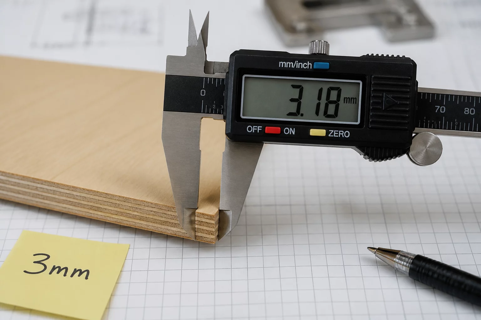
Apply controlled ratchet torque when measuring coupon stacks to avoid compressing fibrous core plies, ensuring reading repeatability within +/-0.005mm.
Operational Calibration Takeaways
Key empirical rules extracted from over three hundred laboratory calibration cycles across acrylic, MDF, and plywood test series.
- Always divide total stack loss by the exact count of cut passes rather than assuming theoretical nozzle specifications.
- Record kerf variations along both X and Y axes independently to compensate for optic astigmatism or asymmetric assist airflow.
- Re-calibrate beam kerf whenever switching between material densities, moisture levels, or lens cleanliness states.
Integrating Measured Values into LightBurn Workflows
Once the empirical kerf width is determined, apply half of the measured value as an outward or inward kerf offset in your cut layer properties. For an interference press-fit, deduct an additional 0.02mm to create firm mechanical friction without causing split laminates.
Keep detailed records of focal distance, air regulator pressure, and measured kerf for each stock batch. Material moisture changes and lens contamination directly alter beam energy density over time.

Laboratory Comments
Casey
Fabrication TechnicianBeam width measurement is tricky, nice guide.
Leave a Laboratory Note
Share technical feedback or empirical observations regarding laser kerf compensation.