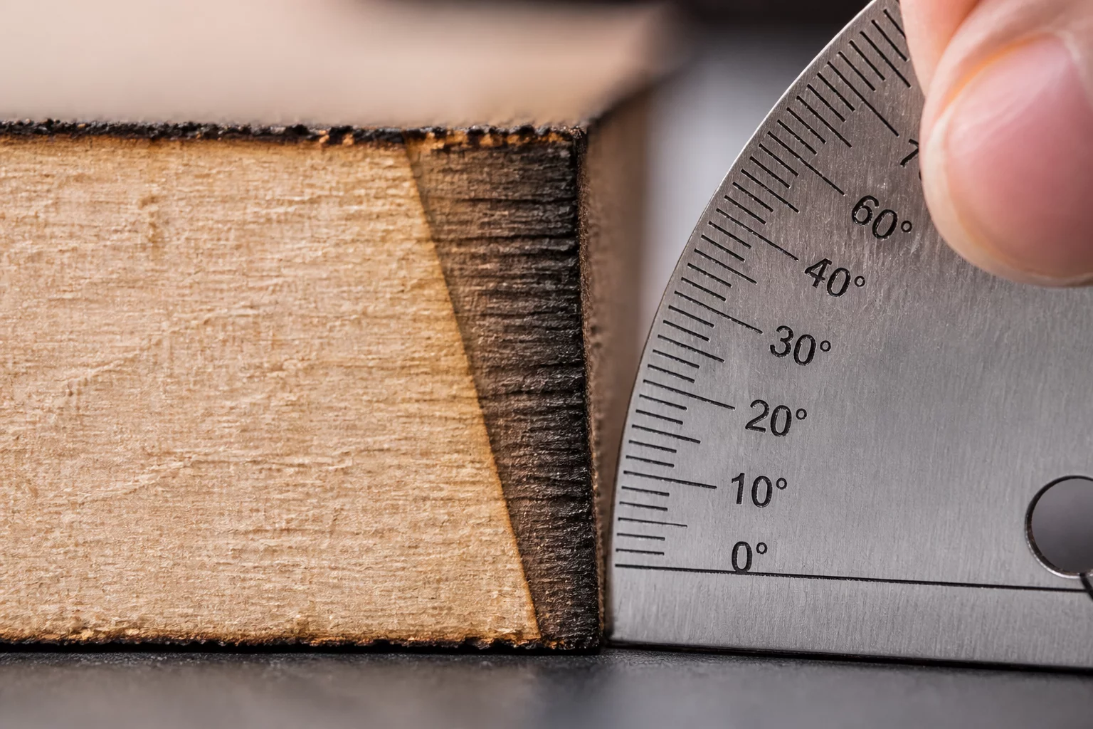
The Hourglass Beam Profile and Edge Beveling
When a laser beam passes through a focusing lens, it converges to a focal spot of minimum diameter and then rapidly diverges. The vertical span across which the beam remains reasonably focused is known as the depth of focus (Rayleigh length). In thick materials such as 6mm plywood or 8mm cast acrylic, this optical reality introduces a measurable taper or V-angle along the cut edge. If the focal plane rests strictly on the top surface, the bottom edge expands noticeably, creating a trapezoidal cross-section that hinders vertical slot mating.
Shifting the focal point into the middle third of the substrate splits the divergence symmetrically between the upper and lower surfaces. In empirical fit test trials, submerging the focus by 1.5mm to 2.0mm reduced edge perpendicularity error by more than 40%. This adjustment equalizes the entry and exit kerf, allowing interference joints and mortise-tenon connections to seat uniformly throughout their full depth.
Critical Principles for Focal Plane Tuning
- 01
Focal Length Determines Taper Severity
Short focal length lenses (such as 1.5 inch) produce a tighter waist with severe divergence, while longer 2.5 or 4.0 inch optics yield straighter vertical walls over thicker stock.
- 02
Submerged Focal Setting Balances Slot Entry and Exit
Setting the beam waist at 30% to 50% below the top surface creates an hourglass cross-section that balances interference fit across top and bottom faces.
- 03
Caliper Readings Must Target Mid-Wall Dimensions
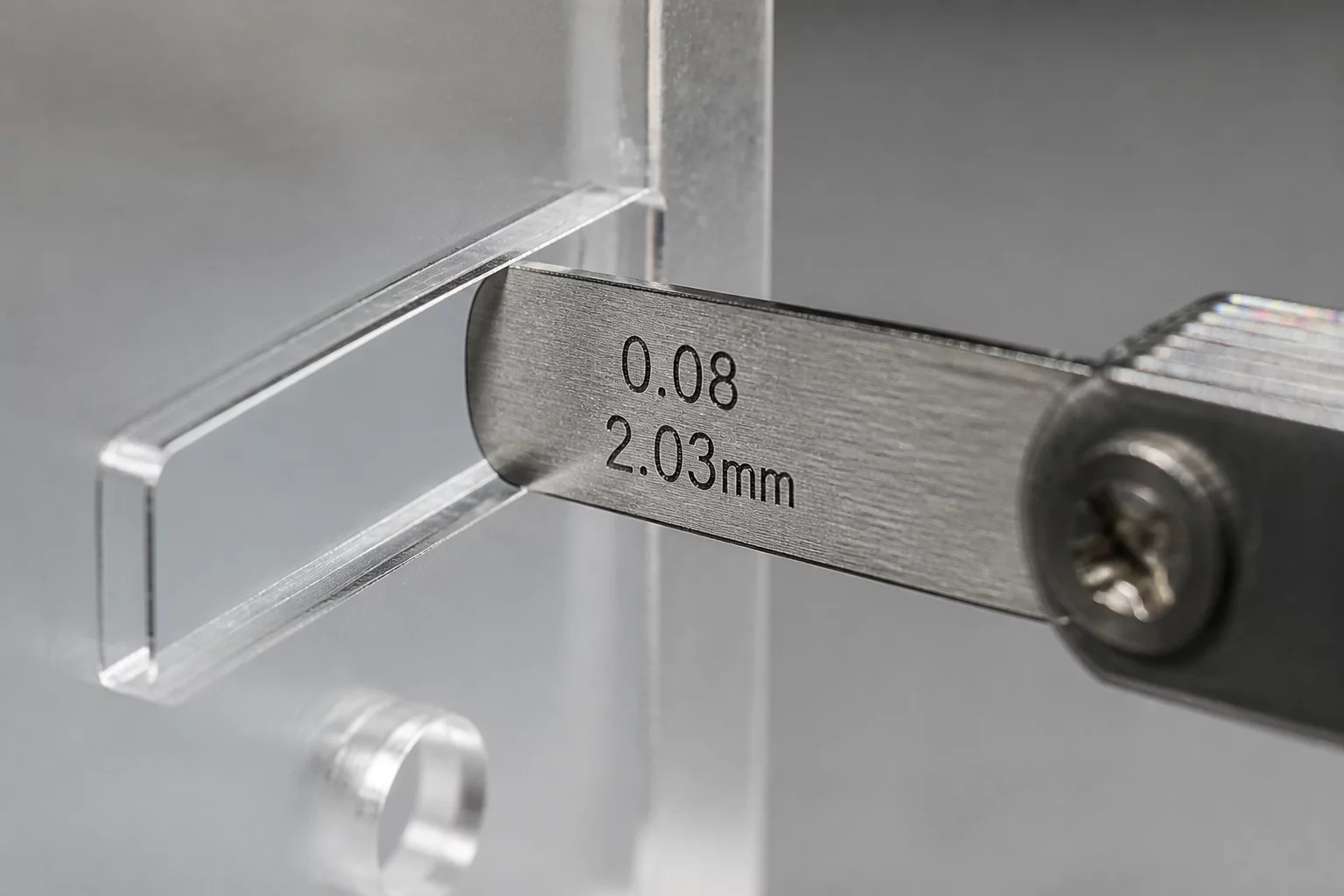
Measuring only the top rim of a cut slot misrepresents the actual mating aperture. Always measure both top and bottom kerf widths to calculate net slant angle.
- 04
LightBurn Kerf Offsets Interact With Bevel Angles
An applied kerf offset shifts the entire perimeter cut line, meaning edge slant directly determines whether opposing angled edges mate smoothly or bind at high-friction contact points.
Bench Takeaways for Precision Slot Joints
Balancing focal depth eliminates binding without requiring excessive kerf compensation adjustments.
- For stock thicker than 4mm, position the focal plane at midpoint or 1/3 depth to equalize upper and lower kerf width.
- Switch to a 2.5-inch lens when cutting 6mm or thicker materials to widen the effective depth of focus.
- Calibrate LightBurn kerf compensation specifically against the mid-depth gauge of test slot coupons.
Step-by-Step Focus Depth Calibration Protocol
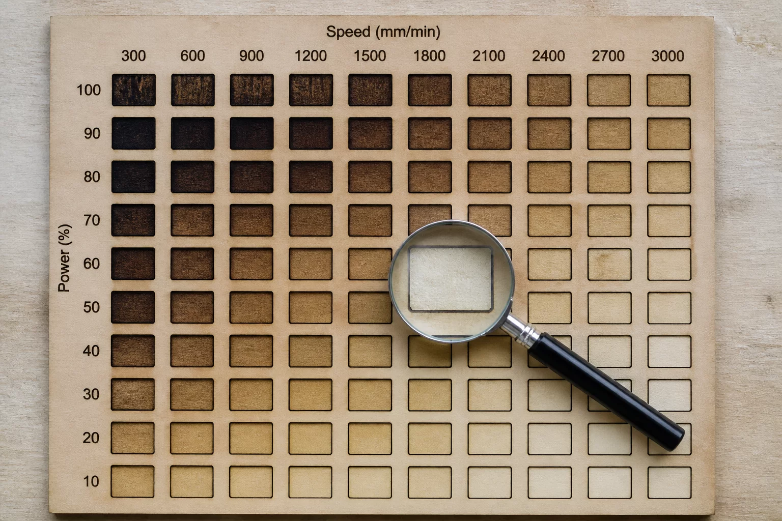
Begin by performing a stepped ramp test to verify the exact focal distance of your lens assembly. Once zero-point is confirmed, prepare three identical slot test coupons in the target material gauge. Cut the first coupon with the focus set directly on the top surface, the second at 33% depth, and the third at 50% depth. Inspect each edge under magnification and record entry and exit slot apertures with gauge pins or digital vernier calipers.
Compare the insertion force required to seat a standard mating tab. The submerged focus coupons consistently demonstrate smoother friction distribution and superior dimensional stability under mechanical load. Record the optimal focal height in your material library alongside the designated LightBurn layer parameters for future production runs.

Laboratory Comments
No laboratory comments yet. Be the first to record an observation.
Leave a Laboratory Note
Share technical feedback or empirical observations regarding laser kerf compensation.