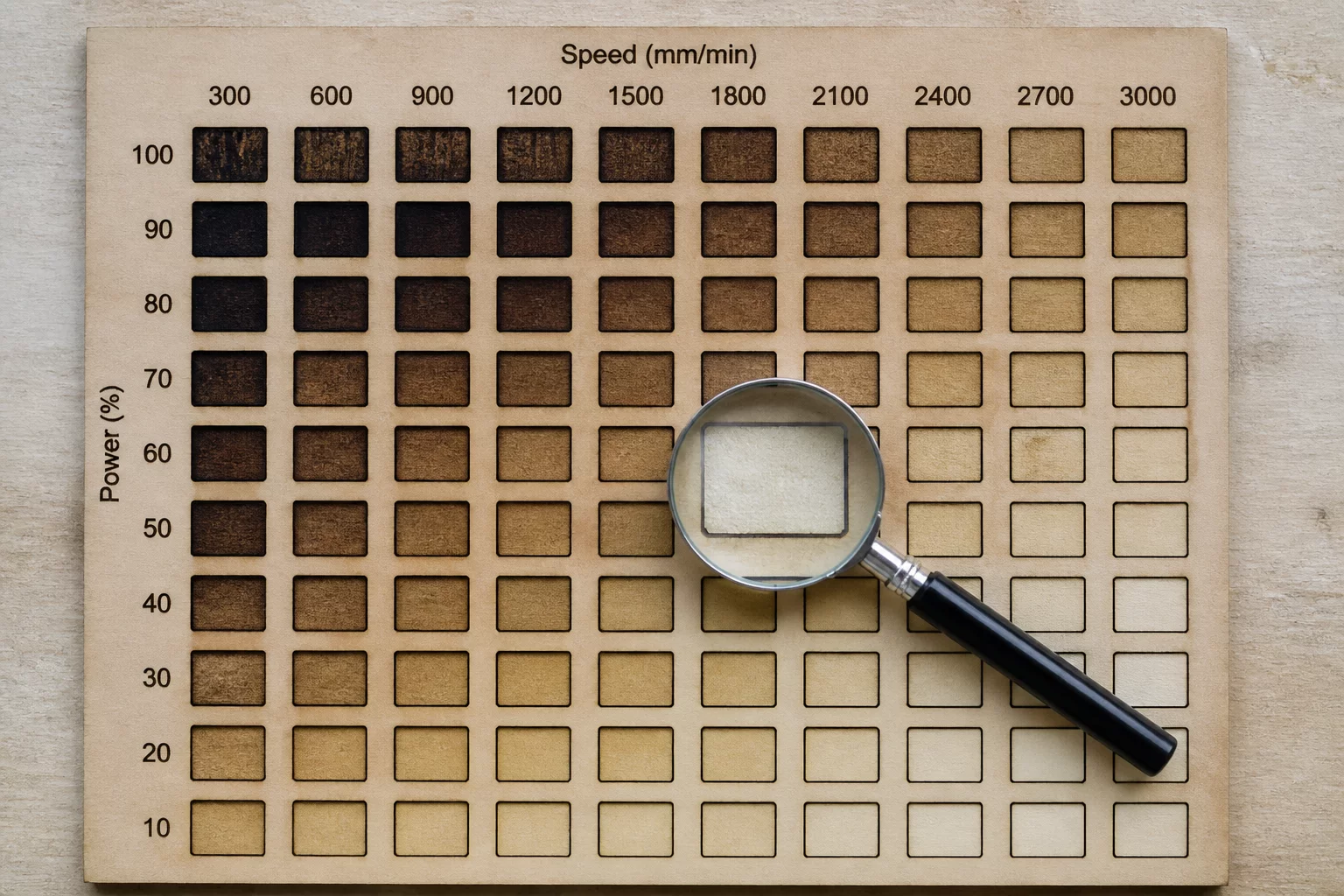
Kinetic Energy Deposition Across Varied Feed Rates
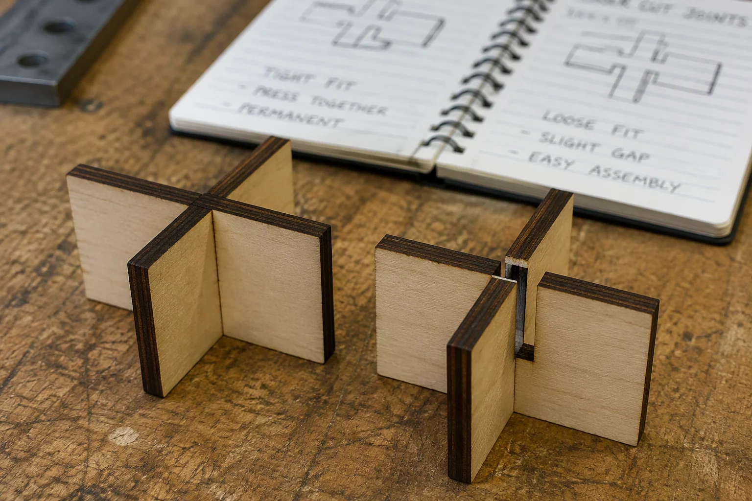
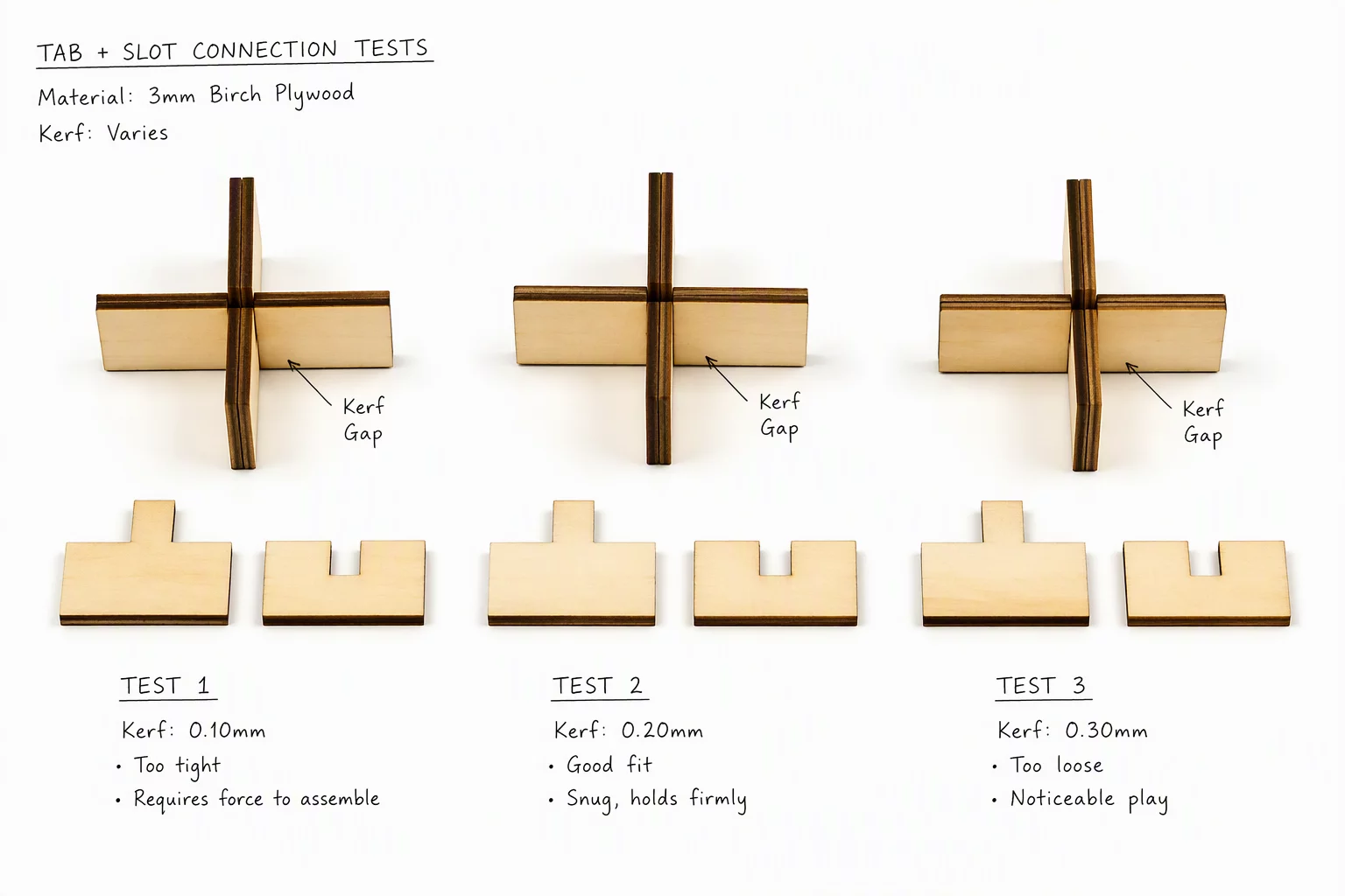
Through controlled stepping tests across 60W and 100W CO2 laser tubes, kerf variation exhibits a non-linear decay curve relative to head velocity. At high cutting speeds (25-35 mm/s), the dwell time of the focused optical spot is minimized, producing a razor-thin kerf of 0.14 mm with minimal heat-affected zones. However, as speed drops below 12 mm/s to ensure clean penetration through denser resin pockets, kerf width widens to 0.22 mm, creating loose, unseated tenons if compensation values remain static.
Power modulation introduces an identical phenomenon. Pushing peak tube power beyond the threshold needed for complete material severance does not increase cut depth proportionately; instead, excess photon flux superheats the kerf channel, charring sidewalls and ablating extra substrate. Achieving repeatable interference joints demands finding the highest sustainable velocity at the lowest stable tube power.
Four Governing Laws of Kerf Modulation
- 01
Feed Rate Inversion Rule
Halving cutting speed at constant power increases measured slot width by approximately 25% to 35% in dense wood composites.
- 02
Excess Power Dissipation
Supplying 15% more power than required for separation causes sidewall burning and increases optical kerf by up to 0.04 mm.
- 03
Corner Deceleration Widening
Stepper acceleration curves cause laser head slowdown at sharp 90-degree corners, naturally widening corner kerf unless dynamic power ramping is enabled.
- 04
Vector Kerf Recalibration
Any change to cutting speed or tube current in LightBurn necessitates a rerun of the five-slot gauge coupon before production nested cutting.
Key Laboratory Benchmarks
When tuning cutting parameters in LightBurn for tight friction fit joinery, apply these verified operational baselines:
- Lock cutting speed and power before measuring kerf compensation values with digital micrometer calipers.
- Utilize min/max power scaling in vector layers to counteract corner deceleration overburn.
- Maintain identical air assist pressure when adjusting feed rates to avoid erratic sideways smoke deflection.
Calibration Workflow for Production Nesting
To establish exact kerf compensation, run a 10-piece step block test using identical speed, power, and air settings planned for the production run. Measure the total accumulated length of the cut strips clamped together, subtract the measured dimension from nominal CAD dimensions, and divide by the number of cuts to calculate true kerf width down to 0.01 mm precision.
Input half of the derived kerf width into the LightBurn Kerf Offset setting (outward for external perimeter tabs, inward for internal mating slots). Test the resulting joint with a single coupon pair before running full nested sheets.

Laboratory Comments
Drew
Fabrication TechnicianNever realized speed affected kerf this much.
Leave a Laboratory Note
Share technical feedback or empirical observations regarding laser kerf compensation.