High-Pressure Ejection Versus Thermal Plume Spread
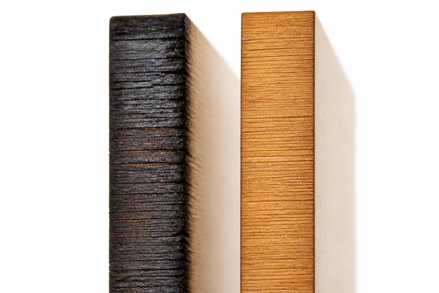
Pressurized gas forced through a focused cone nozzle instantly evacuates carbonaceous debris and combustible vapors from the laser focal zone. High line pressure (2.0 to 2.8 bar) restricts localized open flaming, thereby narrowing the effective heat-affected perimeter. This maintains a crisp, tight beam track. Conversely, low air delivery allows lingering micro-flames to widen the cut trench by an extra 0.04 mm to 0.07 mm, turning intended friction fits into loose, unstable connections.
Beyond lateral kerf expansion, inconsistent gas pressure induces noticeable edge taper along the Z-axis. Coaxial laminar flow clears bottom kerf exits cleanly, whereas turbulent or off-center airflow causes back-pressure vortices inside narrow slots. This asymmetric airflow widens the bottom exit disproportionately to the top entry. When testing tenon and mortise assemblies in LightBurn, setting constant pressure across test coupon batches is vital to prevent false kerf compensation readings.
Pneumatic Principles Governing Joint Fit
- 01
Flare Combustion Suppression
Active air assist quenches open flames at the cutting front, avoiding secondary thermal erosion that unintentionally over-widens mortise slots.
- 02
Asymmetric Nozzle Jet Distortion
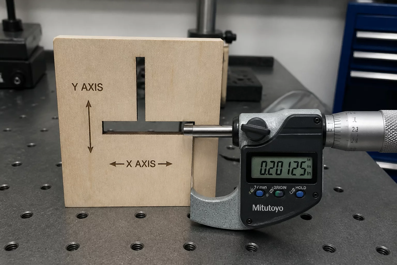
A misaligned cone nozzle deflects gas flow off-axis, producing directional kerf discrepancies between X and Y travel paths.
- 03
Acrylic Polishing vs Wood Ejection
Hardwoods and plywoods require strong pneumatic pressure to expel resinous char, whereas cast acrylic benefits from gentle pressure (0.4–0.8 bar) to maintain flame-polished sidewalls without chill-scalloping.
- 04
Moisture and Oil Line Filtration
Unfiltered air supplies deposit microscopic aerosols onto the final meniscus lens, diffusing spot concentration and randomly widening kerf width mid-cut.
Key Laboratory Takeaways
Air assist dynamics alter both the nominal slot width and vertical wall perpendicularity.
- Maintain steady inline pressure; a drop from 2.5 bar to 1.0 bar widens plywood kerf by roughly 0.05 mm.
- Inspect nozzle coaxial alignment with a thermal tape shot to ensure uniform airflow across all cutting directions.
- Re-run fit test coupons whenever switching between low-pressure diaphragm pumps and industrial compressor lines.
Calibrating Air Flow for Repeatable Friction Tolerances
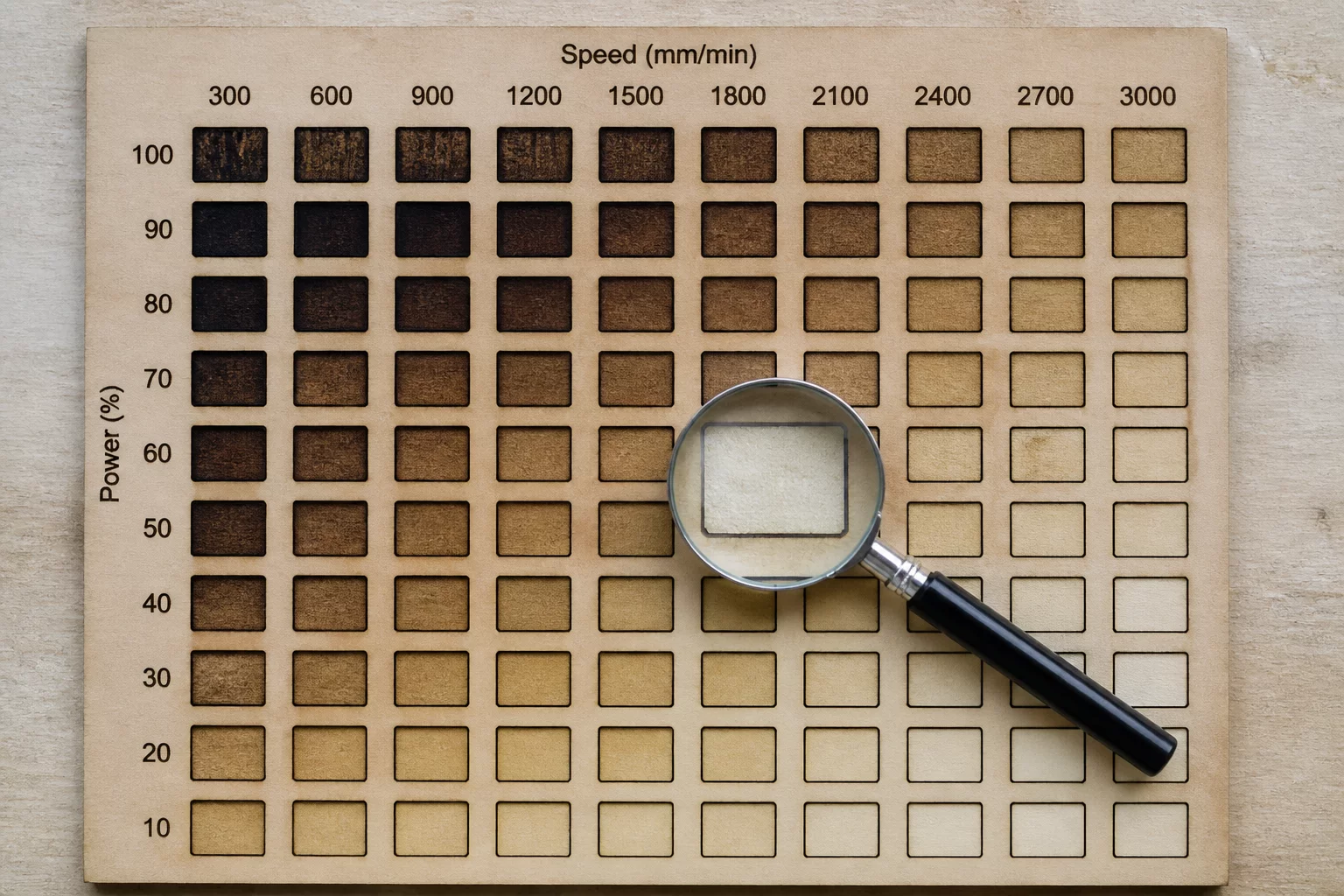
When configuring LightBurn layer libraries, air assist should never be treated as a binary on/off switch. Material test matrices must record exact pressure regulator values alongside speed and power percentages. In multi-pass cutting of dense laminates, high-pressure continuous assist ensures bottom slag ejection, enabling tight press-fit tolerances without secondary hand filing.
Always verify pneumatic line stability before embarking on nested production cuts. Pressure fluctuations during compressor duty cycles create noticeable fit variance between parts cut at the start of a cycle versus those cut during line recharge. Dedicated storage tanks and two-stage regulators eliminate this variance.

Laboratory Comments
No laboratory notes recorded for this calibration log yet. Be the first to submit your observations.
Leave a Laboratory Note
Share technical feedback or empirical observations regarding laser kerf compensation.