Kinematic Dynamics & Optical Polarization Effects
In Cartesian laser platforms, the optical head travels independently along the lightweight X-axis rail, whereas the heavier crossbeam gantry traverses the dual Y-axis tracks. This fundamental difference in moving mass generates subtle velocity ripples and corner deceleration variances. When cutting tight interlocking finger joints oriented across both axes, cuts executed parallel to the Y-axis often burn slightly broader kerfs due to prolonged thermal dwell time during micro-decelerations.
Furthermore, linear CO2 laser tubes emit polarized radiation that reflects differently across delivery mirrors and focal lenses depending on the angle of incidence. The resulting focal spot is rarely perfectly circular; it presents a slight elliptical contour. An elliptical beam creates a narrower cut when traveling along its minor axis and a broader kerf when moving along its major axis. Identifying this dimensional delta prevents unexpected friction imbalances in complex multi-directional joinery.
Core Causes of Directional Kerf Variance
- 01
Gantry Inertia Differential
The heavier Y-axis assembly demands greater acceleration torque, which produces minute dwell lags and micro-vibrations along vector lines compared to the agile X-carriage.
- 02
Beam Ellipticity and Polarization
Uncorrected tube mode polarization creates an asymmetrical waist where the beam diameter along the X plane differs by 0.02–0.04mm from the Y plane.
- 03
Asymmetrical Belt Tensioning
Uneven belt stretch or loose idler pulleys cause directional backlash during vector reversals, translating into skewed slot apertures.
- 04
Air Assist Nozzle Jet Angle
Off-center coaxial assist nozzles push molten resin or vaporized debris unidirectionally, cooling one cut flank faster than the perpendicular flank.
Calibrated Solutions for Axial Balance
Mitigate directional kerf discrepancy through structured testing and software compensation strategies.
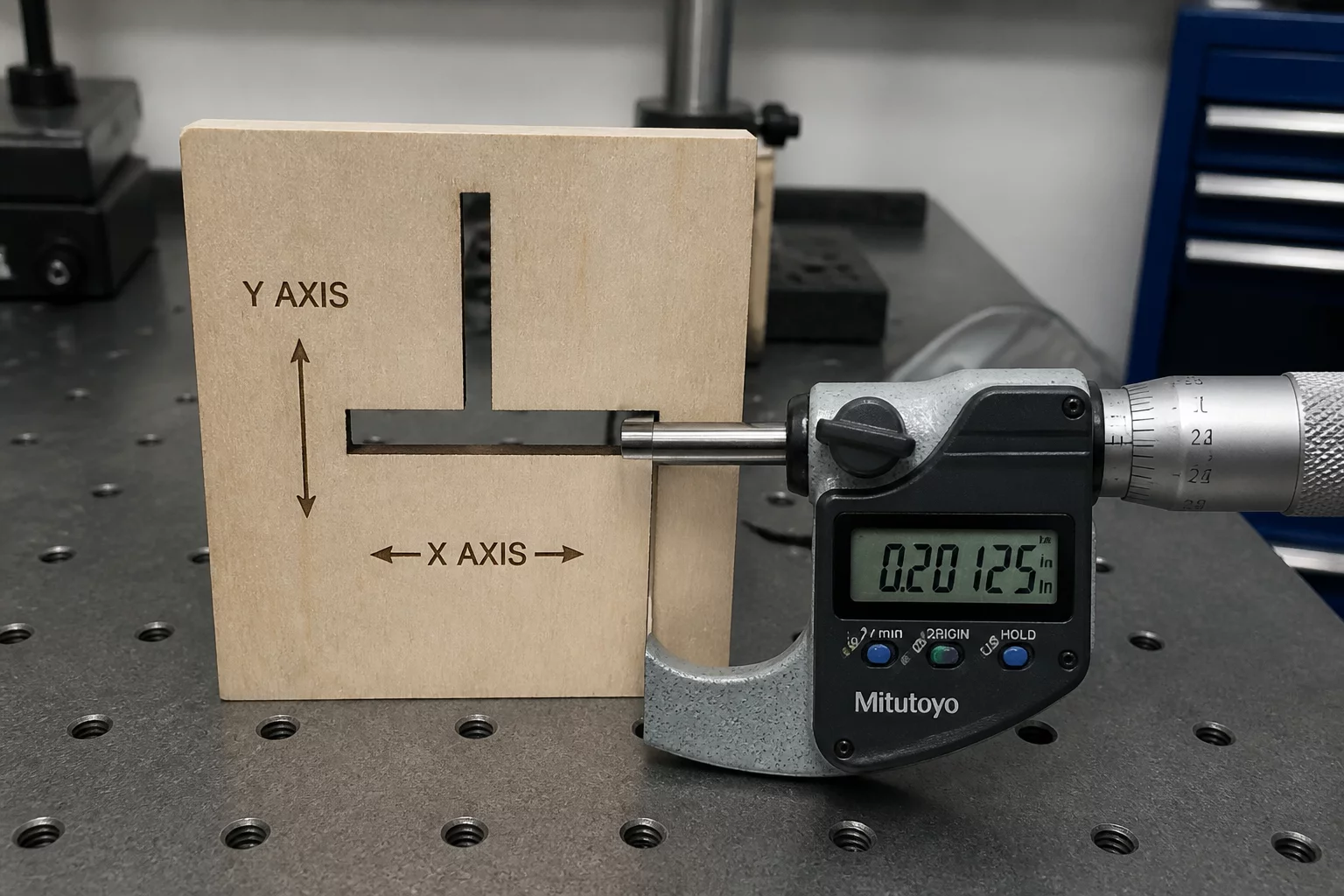
- Cut cruciform test coupons with orthogonal 90° slots to gauge independent X and Y kerf widths via digital micrometers.
- Apply dedicated X/Y kerf offset compensation in LightBurn device profiles when beam astigmatism exceeds 0.03mm.
- Orient critical friction-fit tabs parallel to the axis with the tighter, more repeatable kerf baseline.
Diagnostic Protocol & Test Coupon Layout
To isolate directional anomalies from material grain effects, cut a standardized cruciform test pattern with identical 5.00mm nominal slots oriented along 0°, 45°, and 90° angles. Measure the internal slot widths with pin gauges or precision caliper jaws. If the 90° slot consistently measures wider than the 0° slot regardless of material sheet rotation, the variance is purely machine-driven.
When software does not offer independent axis kerf compensation, adjust the gantry acceleration limits in controller firmware to minimize overshoot on the heavier axis. Inspect delivery mirror alignment to ensure the raw beam strikes the center of the focal lens perpendicularly, eliminating coma aberration and restoring a circular focal point.


Laboratory Comments
Jamie
Fabrication SpecialistDirectional differences explained perfectly.
Leave a Laboratory Note
Share technical feedback or empirical observations regarding laser kerf compensation.