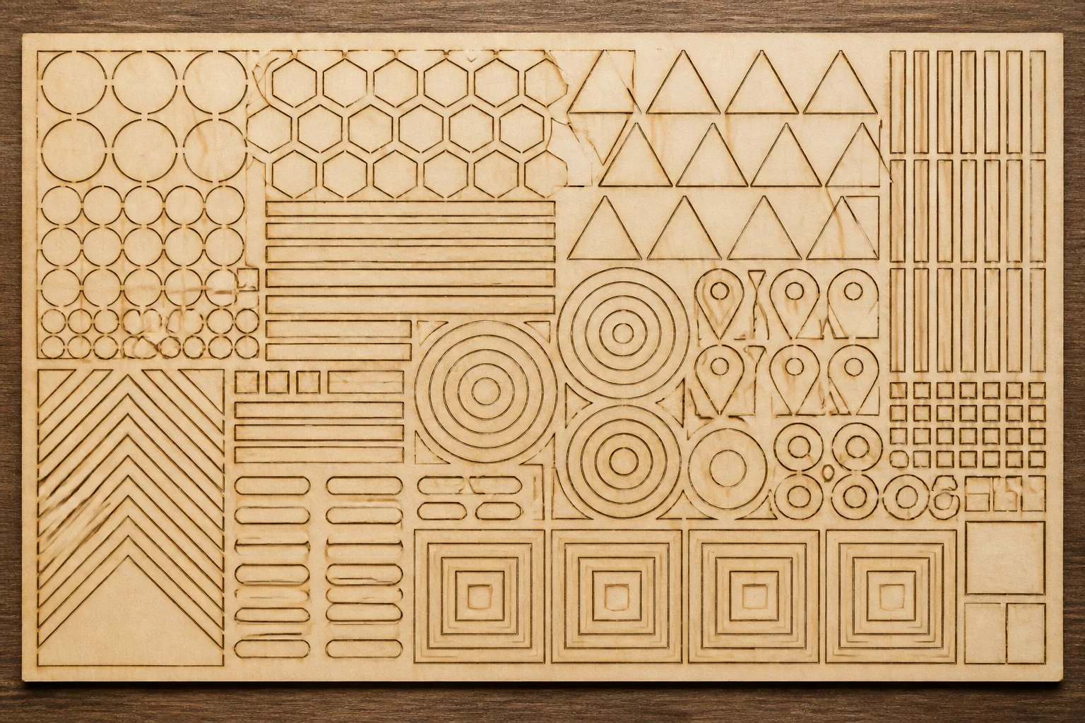
Thermal Accumulation and Structural Web Collapse Dynamics
In automated sheet nesting, closing the gap between adjacent part boundaries maximizes material yield but introduces severe physical hazards. As the focused laser beam traces closely spaced parallel paths, the narrow strip of remaining substrate absorbs concentrated heat from successive cutting passes. When this bridge drops below 1.0 mm to 1.5 mm on organic wood composites or acrylic, the wood fiber chars completely through or acrylic melts back into the adjacent contour, destroying perimeter dimensional accuracy.
To preserve exact edge geometries and prevent interlocking parts from welding together or falling through the honeycomb bed prematurely, part spacing must account for both the physical kerf width and the material heat-affected zone. Executing interior cutouts first and distributing outer perimeter passes across alternate sheet quadrants prevents heat concentration and eliminates localized warping.
Empirical Principles for Multi-Part Nesting Spacing
- 01
Double-Kerf Plus Heat-Affected Zone Margin
Maintain a minimum separation distance equal to twice the beam kerf width plus 0.8 mm (typically 1.2 mm to 1.5 mm total) to prevent adjacent cut trajectories from burning away the dividing wall.
- 02
Common-Line Cutting Calibration
When sharing cut lines between identical rectangles to save cutting time, eliminate kerf compensation on the shared seam and adjust only outer bounding loops to avoid double-width material loss.
- 03
Staggered Path Optimization
Configure cut sequence optimization in LightBurn to process non-adjacent parts rather than contiguous neighbors, granting fragile web bridges sufficient dwell time to cool below ignition temperatures.
- 04
Small Part Tab Retention
Integrate 0.4 mm micro-tabs on lightweight nested elements smaller than 30 mm to prevent air assist turbulence from tilting parts upward into the traveling laser nozzle.
Nesting Protocol Checklist
Summary guidelines for repeatable sheet yield without thermal distortion or perimeter defects:
- Set minimum nesting part-to-part margin to 1.5 mm for 3 mm plywood and 2.0 mm for acrylics prone to heat pooling.
- Never apply standard outer kerf offset to shared interior boundary lines in common-edge layouts.
- Verify honeycomb support spacing beneath narrow bridge lines before executing full-bed batch runs.
Production Nesting and LightBurn Offset Execution
When setting up high-density layouts, isolate inner holes and intricate slots on dedicated primary cut layers before running outer perimeter cuts. This ensures that every joint and tab is cut while the parent material maintains full rigid connection to the outer sheet framework.
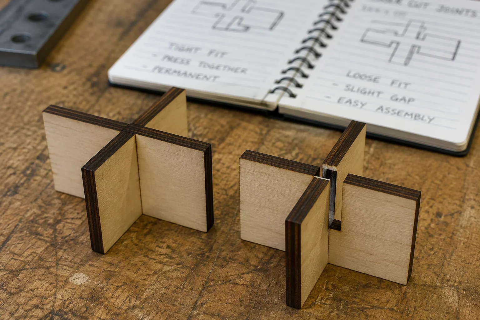
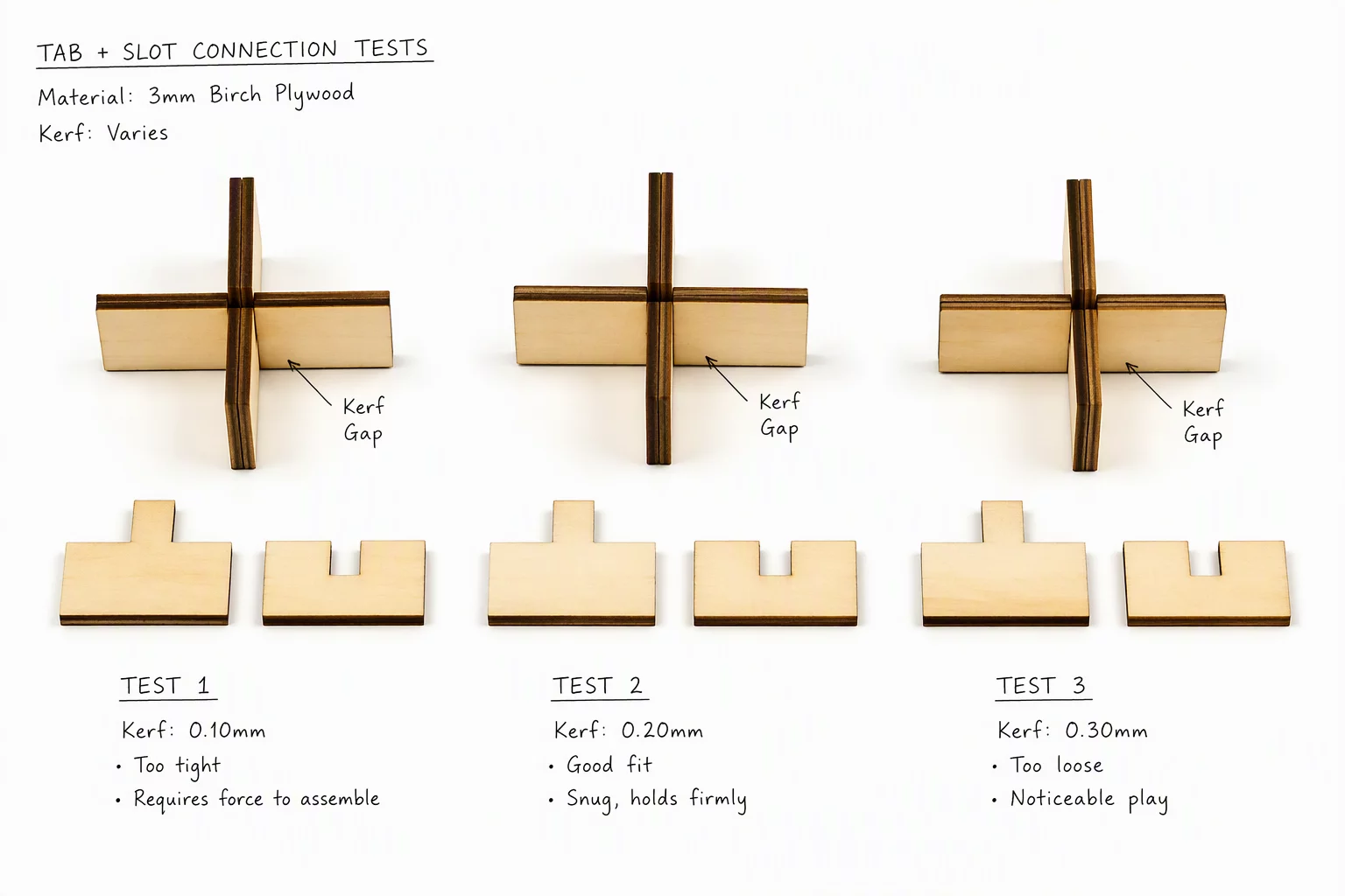
For high-volume cutting, test cut a two-part nest coupon containing the target slot and tab profiles spaced at 1.0 mm, 1.5 mm, and 2.0 mm intervals. Inspecting the central web with calipers reveals whether thermal contraction has pulled the outer boundaries out of square before committing full 600x400 mm stock.

Laboratory Comments
No laboratory comments recorded yet. Be the first to share an empirical observation.
Leave a Laboratory Note
Share technical feedback or empirical observations regarding laser kerf compensation.