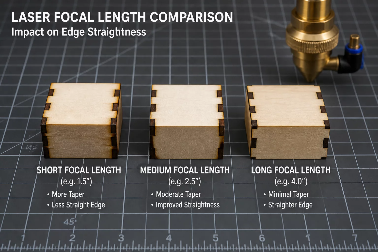
Focal Length Dynamics & Kerf Hourglass Distortion
A standard 2.0-inch plano-convex lens delivers a balanced nominal spot size around 0.12mm with an effective depth of focus of roughly 2.2mm. When processing 6mm Baltic birch plywood, the beam waist sits centered in the material while the top and bottom faces experience slight expansion from the entry and exit divergence cones. Switching to a 1.5-inch lens reduces the spot width down to 0.08mm, dramatically sharpening fine engravings, but introduces pronounced V-shaped edge tapering on any stock exceeding 3mm.
Conversely, testing a 4.0-inch meniscus lens on 9mm hardwood reveals an elongated Rayleigh zone spanning nearly 6mm of near-cylindrical energy distribution. While kerf width expands to roughly 0.22mm, requiring a larger LightBurn kerf offset in your cut layers, the resulting slot walls remain strictly perpendicular at 90 degrees. This geometric consistency prevents friction binding and ensures interlocking tabs seat uniformly across the entire material thickness without requiring manual sanding or filing.
Lens Selection & Kerf Compensation Rules
- 01
1.5-Inch Optics for Thin Stock & Fine Inlays
Produces the narrowest spot size (approx. 0.08mm) for intricate vector cuts under 3mm, but exhibits high divergence that skews slot angles on thicker boards.
- 02
2.0-Inch Optics as the General Workshop Standard
Offers the optimal balance of spot diameter (0.12mm) and depth of field, maintaining dependable joint friction for 3mm to 6mm sheet materials.
- 03
2.5-Inch Optics for Stable 6mm-8mm Connections
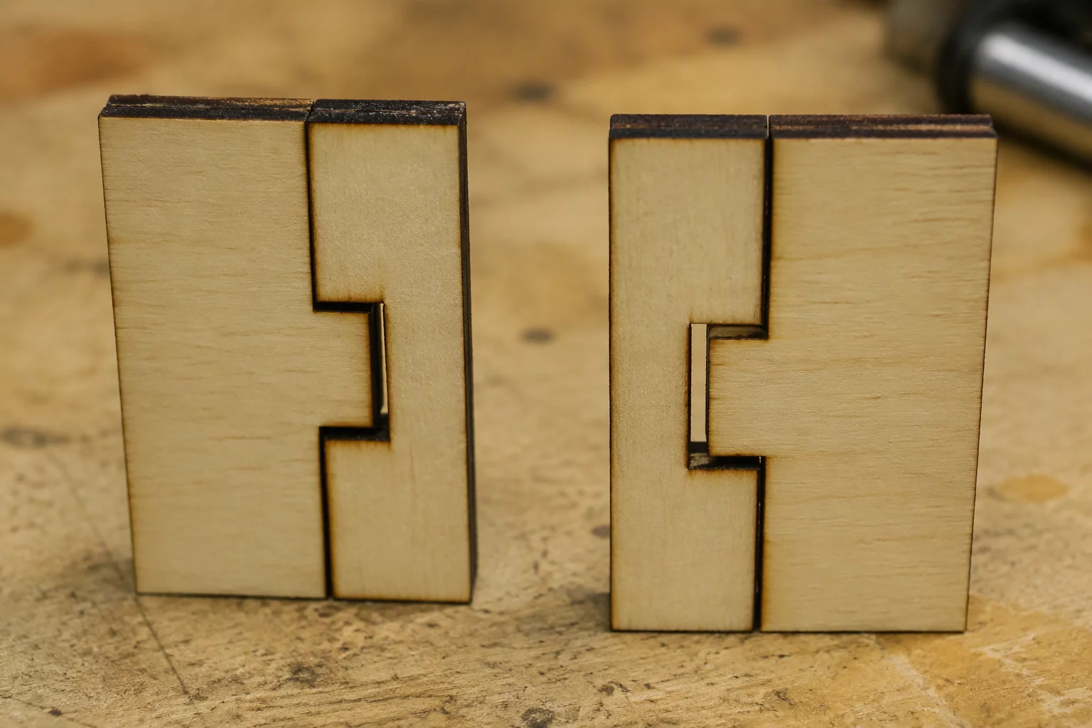
Provides a flatter beam profile through mid-thickness stock, minimizing hourglass taper at slot corners and standardizing caliper measurements across top and bottom faces.
- 04
4.0-Inch Optics for Thick Stock & Perpendicular Edges
Generates a wide beam waist (approx. 0.22mm-0.26mm) with extended focal depth, eliminating edge slant on 9mm to 12mm panels while demanding larger outward offsets in software.
Key Optical Takeaways for Fit Calibration
Never apply kerf offset values calibrated on a 2.0-inch lens directly to projects cut with a 1.5-inch or 4.0-inch optic without running new test coupons.
- Spot width directly sets the base kerf: shorter focal lengths narrow kerf, longer focal lengths widen it.
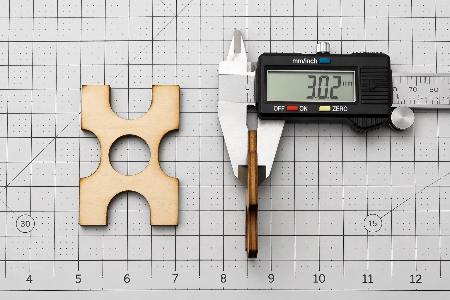
- Hourglass edge profile alters contact pressure: measure joint fit at both the center and outer edges of coupon slots.
- Re-run coupon fit tests whenever optical head focal lenses are swapped or replaced.
Calibrating LightBurn Kerf for Specific Lens Focal Lengths
When configuring layer parameters in LightBurn, identify the exact focal length installed on your laser head. For a 2.0-inch lens cutting 3mm acrylic, input an initial inward or outward kerf offset of 0.07mm, then run a stepped 5-slot test coupon. For a 4.0-inch lens cutting the same material, increase the offset to 0.11mm to account for the broader waist diameter.
Setting the focal plane relative to the material surface also shifts the fit profile. Placing focal point at 1/3 to 1/2 of the material depth balances kerf width between top and bottom surfaces, which equalizes friction across interlocking tenons. Record these focal heights alongside your lens focal length data in your workshop test logs.

Laboratory Comments
No comments yet. Be the first to leave a laboratory note.
Leave a Laboratory Note
Share technical feedback or empirical observations regarding laser kerf compensation.